Starburst Enclosure — Print and Assembly
A thin base plus six straight, interchangeable color bands, with larger fingertip access underneath.
Prototype 03 combines the earlier thin panels into six thick, single-piece bands above a thin base. All star profiles align straight, with no twist and no assembly seams inside a band.
Download current STLs · Open the full-size 3D preview · Assembled STEP (ZIP)
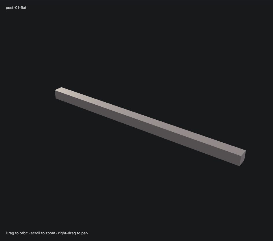
Assembled image · Exploded image · Underside controls · Post in print orientation · Original appearance reference
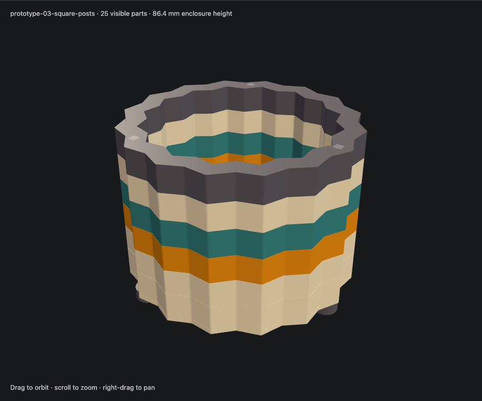
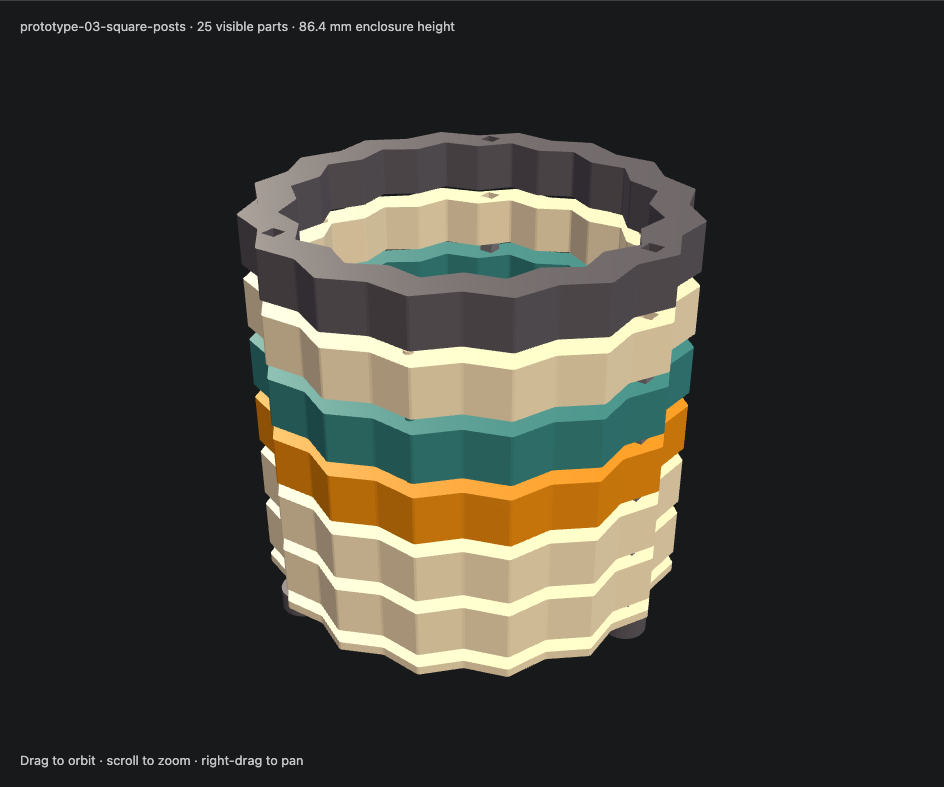
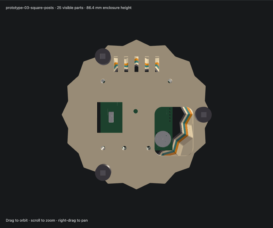
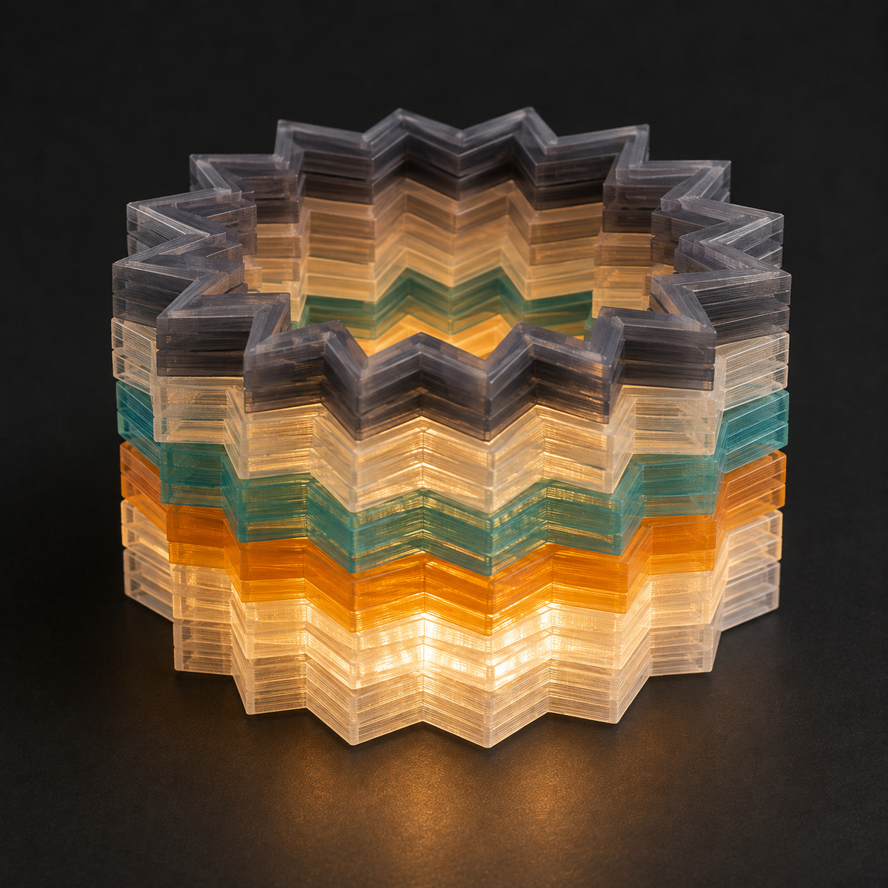
Use Exploded for the six bands, PCB & base for the mounts, and Underside for the enlarged finger opening. Isolate individual parts to download their STLs. The colors illustrate filament choices, not simulated light transmission.
Thin base and six straight bands
The default size is approximately 116 mm across × 86.4 mm high, excluding projecting fasteners. Base thickness is 2.4 mm, band thickness 13 mm, and foot height 6 mm. Locating pins add 1 mm of print height but nest into the next band.
| File | Body thickness | Suggested color | Function |
|---|---|---|---|
00-base | 2.4 mm | Clear | PCB mounting and underside access |
01-band-usb | 13 mm | Clear | Bottom band with USB notch |
02-band | 13 mm | Clear | Interchangeable middle band |
03-band | 13 mm | Amber | Interchangeable middle band |
04-band | 13 mm | Teal | Interchangeable middle band |
05-band | 13 mm | Clear | Interchangeable middle band |
06-band-top | 13 mm | Smoke | Top band, no exposed locating pins |
Bands 02–05 have identical geometry. Print them in any colors and change their order freely. The two clear pieces provide two independent color positions. The first and last bands have distinct functional details; every outer profile aligns.
The ZIP contains 21 assembly parts and eight coupons: seven base/band pieces, eight PCB spacers, three round feet and three printed square posts. The historical filename is retained for existing links, but the contents are v3. Replace the old extracted set rather than mixing revisions.
Connections
Three Ø2.4 × 1 mm pins enter Ø2.8 × 1.35 mm sockets. Their asymmetric pattern keys orientation. The broad band faces meet, with 0.4 mm diametral and 0.35 mm depth clearance at the short pins. Each band prints flat with pins upward; the top band has no upward pins.
Three printed square posts, 4 × 4 × 85.4 mm, pass through 4 × 4 mm square holes in the bands, base and feet. The nominal post and hole dimensions match exactly, as requested. Each post is a plain cuboid exported on its long face: 85.4 × 4 mm bed contact and only 4 mm print height. The preview assembles it upright; selecting an individual post shows its flat print orientation.
The feet are Ø12 × 6 mm printed cylinders with centered square through-holes, without nut pockets. TPU is an option for the feet; use rigid filament for the posts. In the assembly the posts end 1 mm above the bottoms of the feet and flush with the top band. Check insertion depth and foot deformation on the physical print.
This is a fit-based assembly, without metal shell rods, nuts or washers. There is no positive axial lock: straight posts cannot clamp the stack like threaded rods. Support the base when lifting and check for unintended sliding.
Eight coupons cover both interfaces: the four existing short-pin/socket coupons, plus a 20 mm flat square-post coupon and three 13 mm-high hole coupons with 4.0, 4.2 and 4.4 mm square holes. Exact nominal matching may bind in a real print. If needed, --post-clearance 0.2 produces 4.2 mm holes throughout the assembly; 0.4 produces 4.4 mm holes. Default clearance is zero.
Larger fingertip opening
The previous Ø24 mm potentiometer hole is replaced by a 30 × 38 mm rounded rectangular window, with 6 mm corner radii. It extends toward the free side of the wheel to allow fingertip approach and sweeping movement. Its offset preserves the nearby shared PCB post and the web supporting it.
In CAD coordinates, the window spans X14–44 and Y−6–32 mm before corner rounding; the wheel center is approximately (21.9, 18). The switch has its separate 20 × 24 mm opening. Both controls remain recessed underneath. Print the base first and actually turn the wheel by finger; CAD cannot establish comfort.
PCB mounting and USB
Board L LEDs face up and its controls face down. Board P remains below it using xL = xP + 16.5, yL = yP. Hole positions are read from the KiCad files. See Rear Controls for component placement and evidence.
| Spacer | Board L front-view coordinates (mm) | Supports |
|---|---|---|
mount-01-17.6mm | (4, 4) | Board L |
mount-02-17.6mm | (4, 56) | Board L |
mount-03-5.0mm | (20.5, 4) | Board P, shared hole |
mount-04-5.0mm | (29.3, 32.6) | Board P, independent hole |
mount-05-5.0mm | (39.5, 4) | Board P, shared hole |
mount-06-17.6mm | (56, 56) | Board L |
interboard-01-11.0mm | (20.5, 4) | Between boards |
interboard-02-11.0mm | (39.5, 4) | Between boards |
The 11 mm facing-surface gap remains provisional: measure the naturally seated header pair before clamping. Do not pull the boards into an assumed spacing with screws. An underside view mirrors left/right visually; do not mirror the STL files.
The bottom band has an 18 × 13 mm full-height USB notch. The next band closes its roof during assembly, so a wide horizontal bridge need not be printed. The cable check reserves a 16 × 8 mm overmold corridor to the PCB edge and an 8.4 × 2.6 mm metal-nose corridor; actual insertion still needs physical verification. The open top and base slots provide airflow, with powered thermal testing pending.
Printing and assembly
Print pin/socket coupons in the intended filament. The 0.4 mm-clearance socket matches this version. Adjust
socket_diameterand regenerate if needed.Print the base and spacers; dry-fit the boards and test actual fingertip adjustment.
Mount Board P on three 5 mm spacers and secure its independent hole. Fit the two 11 mm interboard spacers, three 17.6 mm Board L supports, then seat Board L LEDs up.
Print each band flat as a separate Bambu Studio object, pins upward. No extra rotation is required. Each band can use any color; an AMS is optional.
Print the long cuboid posts lying flat in the supplied STL orientation. Print the round feet flat, optionally in TPU. Slide feet, base and bands over the square posts; set the post bottoms 1 mm above the feet bottoms. Test retention.
PCB hardware starting point: five M3 × 25 mm nylon screws, one M3 × 14 mm nylon screw and six nylon nuts. Check thread engagement and adjust for your hardware. The shell connection posts and feet are now printed; no metal shell fasteners are required. The PCB mount still uses the nylon screws listed above. The preview does not model PCB screw threads or actual solder.
Start with the selected PETG profile, a 0.4 mm nozzle, 0.2 mm print layers and at least three walls. Compare one thick band first: solid/100% infill is an optical starting point, not a tuned prescription. Inspect the short locating-socket bridges and avoid supports inside locating sockets. Follow filament/plate instructions and Bambu's transparent PETG guidance.
Source and verification
The source is enclosure/. uv installs pinned CadQuery and trimesh in an isolated environment; KiCad exports the placed board/component geometry. No desktop CAD application is needed to print these STLs.
uv run enclosure/generate.py
# Optional measured facing-board gap:
uv run enclosure/generate.py --board-gap 11.0
# Optional square-hole fit adjustment after the coupons:
uv run enclosure/generate.py --post-clearance 0.2
cd doc
pnpm generate:enclosure-viewer
pnpm build
The manifest records dimensions, placements, source/mesh hashes and verification results. It takes precedence over these default dimensions after a custom regeneration. Checks cover connected print bodies, watertight meshes, Z=0 placement, PCB mounts and connector alignment, assembled interference and cable clearance. The docs build rejects stale source/mesh hashes. Reference component meshes are excluded from the print ZIP.
The assembled-fit verdict remains NEEDS BENCH: verify actual seating, cable fit, fingertip operation, solder/lead clearance, optical appearance and temperatures. Existing component evidence and limitations are retained in Rear Controls. The previous Board P guide correction on Board L (Edge.Cuts → Dwgs.User) remains; this revision does not move components.