Rear Controls — PCB and Enclosure Handoff
The stopped ALPS wheel and short slide switch, their rear placement and remaining mechanical checks.
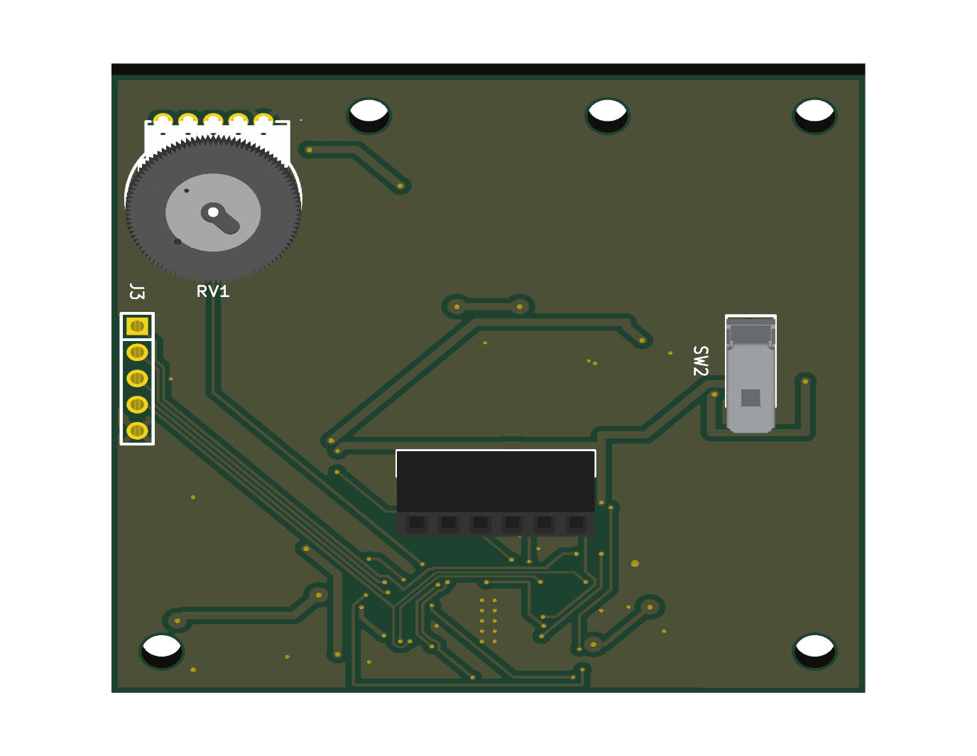
The 24 LEDs face the light chamber. On the opposite face, RV1 ALPS RK10J11E0034 / C470643 provides absolute brightness with physical stops, and SW2 G-Switch SS-12D01-G020 / C5446803 provides maintained power ON/OFF. The tall encoder and toggle are superseded.
Placement and height
Coordinates use KiCad's front-view axes on the 60 × 60 mm Board L outline. An underside view mirrors X; do not mirror these coordinates again in mechanical CAD.
| Feature | X (mm) | Y (mm) | Placement |
|---|---|---|---|
| RV1 footprint origin | 51.90 | 9.50 | B.Cu, 0° |
| RV1 wheel centre | 51.90 | 12.00 | Offset from footprint origin |
| SW2 footprint origin | 9.10 | 27.75 | B.Cu, 90° |
| J2 centre | 29.40 | 37.70 | Existing six-contact mating alignment |
RV1's knob is Ø14 ±0.2 mm, with approximately 1.97 mm model reach above its mounting plane. Use the entire wheel envelope, not just the footprint origin, for enclosure access and Board P clearance. The manufacturer lists insertion (t:2 mm); the project PCB is 1.6 mm. Catalog wording alone does not qualify retention, seating or soldering on this thickness. Check the actual part and opposite-face lead protrusion before fabrication release; do not silently change all board thicknesses to match an ambiguous catalog label.
The imported ALPS model has a dual-unit family name but its external geometry is checked against the selected single-unit drawing. The single-unit electrical mapping is separate: five lower positions include endpoints 1/3, central wiper 2, and two dummy terminals. Two additional upper supports complete seven physical mounting features. All four dummy/support terminals remain electrically isolated.
SW2's corrected G020 family model uses a 3.5 mm case, 2 mm actuator and retained 0.5 mm shoulder: approximately 6 mm mounted height. Reserve actuator travel, finger access and clearance from the table. Family CAD is an enclosure aid, not proof of exact manufactured dimensions or assembly fit.
Board P and the pillars remain fixed
The Board P outline occupies X 16.50–43.50, Y 0–40 mm in Board L coordinates. The shared upper pillars fix the transform xL = xP + 16.50, yL = yP. Board P's holes (4,4) and (23,4) align with Board L's (20.5,4) and (39.5,4). The third Board P hole projects to (29.3,32.6) and is not a shared through-hole. Board P, pillars and J2 orientation/alignment are unchanged by this control revision.
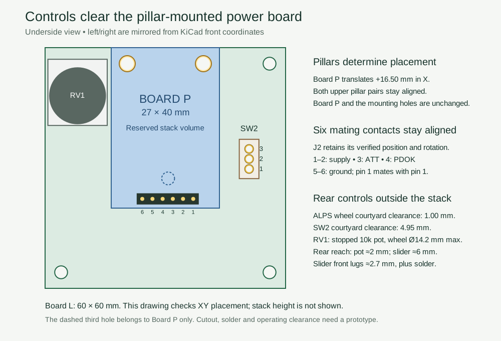
J2 pin 1 remains at X23.05 and pin 6 at X35.75, all at Y37.70 mm. Confirm all six mating contacts, pillar height and connector seating on the assembly. Check both rear body clearance and front lead/solder clearance against LEDs and the chamber.
Electrical and firmware handoff
RV1.1 is GND, RV1.3 is V3P3 and RV1.2 is BRIGHT_WIPER. R27 (100 Ω) feeds BRIGHT_ADC at PA0/ADC_IN0; R22 (100 kΩ) and C22 (100 nF) shunt that node to GND. R23/R28/C23 are removed and PA1 is unconnected. See Board L for calibration, averaging, direction and startup requirements.
SW2 common 2 receives V15_FUSED, throw 1 feeds V15, and throw 3 is isolated on the PCB but live in OFF. Board P remains powered. The power-switch procedure retains the back-power, switching transient and rail-decay checks.
Run KiCad DRC with zone refill and schematic parity, plus the control-placement checker, after the final routed board is saved. Record that revision's actual results; this handoff does not assert new DRC counts. Prototype gates remain mechanical fit, absolute ADC endpoint/direction checks, acquisition settling, smooth dimming, safe startup, thermal behavior and assembled OFF operation.